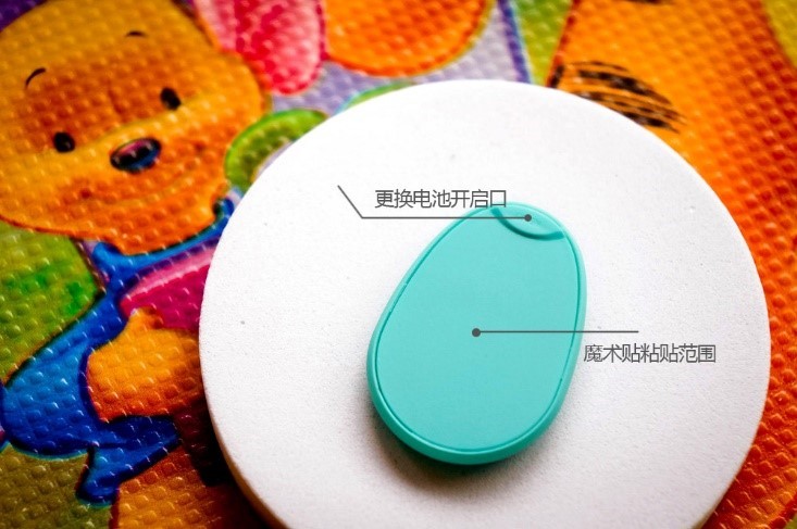
The traditional functions of pull-ups.toddler pants have gradually met the basic needs of consumers, but consumers' consumption concepts are also constantly changing. In order to meet more needs of consumers, the concept of smart products is proposed. Intelligent products not only require absolute quality of the product itself, but also be excellent in hardware and software. In this, the role of sensor design is very important, but because of the too many details involved, this article will focus on the The power module briefly describes its design for reference.

In the system testing device, the power supply design is almost a key link in the normal operation of the product and the testing quality. In this paper, an accurate voltage value needs to be ensured between the working electrode and the reference electrode of the sensor. The voltage reference of analog-to-digital conversion will affect the accuracy of data acquisition, so the voltage range of each module in the system needs to be considered. In the design, the detection device uses lithium battery as the overall power supply, and designs the lithium battery charging and discharging circuit; the microprocessor, operational amplifier, power chip, display screen and other component modules use 5V power supply; the wireless communication module uses a stable 3.3V power supply ; The potentiostatic circuit and 24-bit ADC use the 2.5V power supply as the virtual sum voltage reference.

In the whole system, the detection device is always used to monitor the occurrence of urination and needs to run for a long time. Lithium battery power supply is an ideal way. Lithium batteries are small in size, light in weight and large in capacity, and are widely used in portable devices such as mobile phones. The input voltage range of the charging chip in this paper can be relaxed to 3.7V~6V, and it can work normally without external FET or diode, which simplifies the circuit design. When the operating temperature reaches the upper limit, in order to protect the battery, the charging current will gradually decrease. The POK pin in the chip can be used as a charging indicator, when the chip is connected to any power source, the pin will be pulled down. At this time, an external light is emitted. The cathode and anode of the diode are connected to the power supply together, and it will glow when charging, indicating that the device is charging.
According to the above description, due to the design of the power supply switch circuit, there are two power supply voltages of 3.7V and 4.3V, but most devices, including microprocessors, require a stable 5V power supply. At the same time, power output fluctuations and sudden changes in load will cause system detection errors, and it is necessary to ensure the accuracy of detection during the system detection process. Therefore, the buck-boost switching power management chip is used in the design to support a wider voltage input range.
In this design, the power supply voltage of the lithium battery is only 3.7V, which cannot meet the power supply requirements of most modules in the system. Therefore, the selected power management chip is used for boosting, and its external pin connection circuit is shown in Figure 3.8. The voltage input range of the chip is 2.7V~38V. As the input voltage and load conditions change, the internal circuit automatically selects the conversion ratio to control the corresponding output voltage without additional inductors, and the buck-boost efficiency can reach 95% and 91%. In addition, since the system requires analog and digital power supplies, the output pins of the chip are isolated with inductors, the output voltage is denoised with capacitors, and the analog and digital resistors are isolated to obtain a small and stable output voltage. The chip can achieve different output modes through different high and low levels of the SEL1 and SEL2 pins.

Since the smart pull-ups and toddler pants devices have data acquisition and analysis functions, in the power supply design, the charging time should be as short as possible and the running time should be longer, so as to ensure the normal use of the product. Therefore, there is still room for further improvement of intelligent products.
Comment(0)
You can comment after
SIGN IN